Adam Jones Continued Executive Education Planning and Cloud Focus

A few years back, I put a priority on spending one hour every day towards continued education. Over that time, I have gained so much and fine-tuned my planning further. Within with my ongoing education, I have dedicated a deep focus in Cloud Technologies. I truly believe that Cloud Technologies will bring us into the next Industrial Revolution, providing us the platform and toolsets to solve some of our most challenging problems. The possibilities are endless.

Continued Executive Education Planning

Adam Jones Continued Education Planning.jpg
Adam Jones Cloud Cloud Focus.jpg

Converged Infrastructure Discipline Lead for the Americas

Recently, I accepted a position as the Converged Infrastructure Discipline Lead for the Americas within EMC. I have been so fortunate to work at such a great company with such great individuals. The last 5+ years at VCE has been my favorite time within my career. Last week was my first week and I am still getting up to speed along with developing the framework. I am very much looking forward to the role and all that it entails. Below, I have included a few details in reference to the Converged Infrastructure Discipline Lead for the Americas role. 

  • Technical SME for discipline members both internal and external to EMC proactively assessing methods and procedures 
  • Responsible for the identification of skill gaps and the development of a readiness plan for discipline members based on new or existing products and services
  • Collaboration with delivery team members in their discipline to develop and refine methodologies, standards and best practices
  • Identification of key certifications by role for critical skills within the discipline
  • Foster communities within discipline to promote sharing across members of best practices, standards and methodologies
  • Ongoing regular communication and discipline leadership to members
  • Collaborate and share with peer discipline leaders around the globe to assist with consistency across EMC Professional Services
  • Partner with the field to help support key customers, or early adopters of new offerings
  • Collaborate with the P&SA team, EMC business units and the portfolio team to ensure the awareness of new product and service introduction
  • Provide input and feedback on behalf of the delivery teams to the portfolio and business units around product and service offering development
  • Partner with the geographic leadership to understand reoccurring delivery quality challenges and develop programs to proactively improve delivery quality within their discipline
  • Proactively evaluate the resource capacity and skills pyramid within the discipline and build strategies for further optimization in service delivery
  • Identify and qualify key partners who can assist with service delivery based on in house skill gaps
  • Identify key areas of investment and growth for the discipline based on inputs from the business units, portfolio, delivery, sales and market trends
  • Facilitate the appropriate training and readiness through boot camps, pilots, training and community calls events
  • Partner with Human Resources to define meaningful career paths and growth opportunities by role within the discipline
  • Identify, interview, and qualify partners aligned with discipline and records within the Partner Qualification Catalogue
  • Support partner readiness through collaboration with partner management team and sharing of delivery artifacts, training, tools and best practices

Data Center Design and Analysis with future facilities 6SigmaRoom

Data Center thermal analysis has always been of great interest to me. Last year, I conducted Vblock and VNX DAE Thermal Imaging, which was very beneficial. Over the next few months, I plan to start working with a very detailed data center design and analysis suite called 6SigmaRoom (Computational Fluid Dynamics) from future facilities. Below, I have included two short videos that I have posted to YouTube, along with photos in reference to general capabilities. To get started, I will be utilizing the Lite version, which has a 30-day trial to start digging deep into the product. Products like this represent the framework to take data center design and analysis to the next level. 

future facilities solutions are used by design firms and owners/operators alike throughout the data center's lifecycle to ensure availability, capacity, and efficiency. future facilities ACE Performance Score provides a visual measure of these three interrelated variables in one holistic metric. future facilities are part of a working group at The Green Grid that is developing a standard for measuring such performance, just as PUE currently looks at efficiency. The PDF link below explains ACE and how Bank of America has used it to save over $10M.

From Compromised to Optimized - An ACE Performance Assessment Case Study PDF (Select to Download)

  • future facilities 6SigmaRoom

  • Data Center Thermal Analysis Example

  • Laptop Thermal Analysis Example

Certified Data Centre Design Professional (CDCDP)

I plan to start another certification after having the Schneider Electric Data Center Certified Associate Certification completed by Friday June 12th and the Schneider Electric Professional Energy Manager Certification completed by Friday June 26th. The Certified Data Centre Design Professional (CDCDP) track is one of the most prestigious certifications in the area of Data Center design. There are so many areas in reference to improvement and optimization of physical data center infrastructures. There are very few in the world that have the intimate knowledge of data center computing/storage/connectivity/software coupled with physical data center design. I have always worked in both of these core areas but I strongly believe that this is the next step in my professional development. The complete training track and certification is $5,750.00 and runs for 7 consecutive days. In co-location data centers, it’s all going to be about optimizing every physical component within a data center.  I strongly believe that this track/certification would go a long way in reference to next generation data center design aligning with LEED Certified Facilities.

Certified Data Centre Design Professional (CDCDP)

http://www.cnet-training.com/data-centre-courses/certified-data-centre-design-professional-cdcdp/

Program Overview

Learn how to scope, plan and implement a Data Centre design to meet the ever expanding demands of today’s modern business environment. Utilizing current industry best practices and applicable standards across the key Data Centre infrastructures.

The program has a comprehensive agenda that explores and addresses the key elements associated with designing a Data Centre. It teaches industry best practice principles for the design, construction and operation of computer rooms and Data Centre facilities. The program also breaks down and addresses the requirements of a successful design to meet the business needs incorporating the key infrastructure elements of the physical infrastructure, electrical distribution systems, air-conditioning, data cabling and building support systems. It concludes with a comprehensive case study exercise that leads delegates through the design steps from initiation to commission, covering the business decisions, design scope and implementation phases that need to be addressed throughout the design configuration process.

Industry best practices are achieved by bringing together the direction and guidance from British, European, US and International standards. The CDCDP program content is continually updated to reflect the current Data Centre industry design practices and supporting technology. The CDCDP program is a classroom based and led by one of CNet Training’s expert instructors.

Delegate Profile

The program is designed for individuals involved with, or responsible for an existing data centre, or those looking to achieve best practice when designing and implementing these facilities. Suitable for those with experience in the data centre sector, the program covers in-depth issues on a wide range of relevant topics and is consistently updated to reflect the latest trends and developments.

Program Duration

  • The Certified Data Centre Design Professional (CDCDP) program is 7 days in duration, however it can be split into two units and taken separately:
  • The Certified Data Centre Design (CDCD) – Core Unit is a 3 day unit
  • The Certified Data Centre Design (CDCDP) – Professional Unit is a 4 day unit

Program Objectives

  • Students gain a comprehensive insight into the essential elements of data centre design and how to address them in a variety of situations and applications.

You will also gain the following:

  • The Certified Data Centre Design Professional (CDCDP) Certification
  • A Level 5 BTEC Advanced Professional Qualification in Data Centre Design

Certified Data Centre Design Professional Program Information PDF (Select to Download)

Schneider Electric Data Center Certifications

I always attempt to stay ahead and tie as many computing, storage, connectivity and data center based concepts together. Over the last two years, I have been studying heavily in reference to physical data center designs (emphasis on LEED Certified Facilities). I posted an entry on my engineering blog last year (Cisco Allen Data Center Interactive Tour - http://socal-engineer.com/computing-blog/2014/4/14/cisco-allen-data-center-interactive-tour) in reference to these topics. This compilation came from publically available Cisco resources and provides as nice walk through of a modern day data center. Below, I have provided information in reference to two Data Center certifications that I am obtaining (The Schneider Electric Data Center Certified Associate and Schneider Electric Professional Energy Manager Certifications. The course fees for both tracks are free + exam fees. I plan to have the Schneider Electric Data Center Certified Associate Certification completed by Friday June 12th and the Schneider Electric Professional Energy Manager Certification completed by Friday June 26th. Given my current schedule, a majority of the courses, studying and exams will be completed during the weekends.

Schneider Electric Data Center Certified Associate Certification DCCA Study Guide PDF (Select to Download)

http://www2.schneider-electric.com/sites/corporate/en/products-services/training/energy-university/data-center-certificate-program.page

Course Fee: Free

Exam Fee: $250

Certification Never Expires

Course Lessons

  • DCCA Exam Overview
  • DCCA Course Transcripts - Study Guide
  • Fundamentals of Availability
  • Examining Fire Protection Methods in the Data Center
  • Fundamentals of Cabling Strategies for Data Centers
  • Fundamentals of Cooling I
  • Fundamentals of Cooling II: Humidity in the Data Center
  • Fundamentals of Physical Security
  • Fundamentals of Power
  • Generator Fundamentals
  • Optimizing Cooling Layouts for the Data Center
  • Power Redundancy in the Data Center
  • Power Distribution I
  • Physical Infrastructure Management Basics
  • Rack Fundamentals
  • Choosing Between Room, Row, & Rack Based Cooling For Data Centers I

Schneider Electric Professional Energy Manager Certification - PEM Study Guide PDF (Select to Download)

http://www2.schneider-electric.com/sites/corporate/en/products-services/training/energy-university/energy-efficiency-certificate-program.page

Course Fee: Free

Fee: $400

Certification Valid for 3 years

Course Lessons

  • PEM Exam Overview and Study Guide
  • Active Energy Efficiency Using Speed Control 
  • Boiler Types and Opportunities for Energy Efficiency 
  • Building Controls I: An Introduction to Building Controls
  • Building Controls II: Control Sensors
  • Building Controls III: Introduction to Control Loops.
  • Building Controls IV: Two Position and Floating Responses
  • Building Controls V: Proportional and PID Responses
  • Building Controls VI: When to Use Each Response
  • Building Controls VII: Interactive Illustration of PID Response
  • Building Controls VIII: Controllers and Controlled Devices
  • Building Envelope Metric Version
  • Building Envelope-US Version
  • Combined Heat and Power
  • Combustion Processes
  • Commissioning For Energy Efficiency
  • Compressed Air Systems I: An Introduction
  • Compressed Air Systems II: Compressor Types
  • Compressed Air Systems III: Controlled Methods
  • Compressed Air Systems IV: Supply Side Components
  • Compressed Air V: Efficient Management and Utilization
  • Compressed Air VI: Seven Steps to Better Efficiency
  • Demand Response and the Smart Grid
  • Distributed Generation
  • Efficient Motor Control With Power Drives Systems
  • Electrical Concepts
  • Energy Audits
  • Energy Audits Instrumentation I: Electrical, Lighting, Temperature and Humidity Measurement
  • Energy Audits Instrumentation II: Pressure, air flow, water flow, combustion testing, RPM, compressed air leak detection, and general audit instrument
  • Energy Efficiency Fundamentals
  • Energy Efficiency with Building Automation Systems I
  • Energy Efficiency with Building Automation Systems II
  • Energy Rate Structures I: Concepts and Unit Pricing
  • Energy Rate Structures II: Understanding and Reducing Your Bill
  • Energy Procurement I: Options in Regulated and Deregulated Markets
  • Energy Procurement II: Introduction to Hedging in Deregulated Markets
  • Energy Procurement III: Balanced Hedging Strategies
  • European Codes and Standards: New Horizons for Buildings
  • Fan Systems I: Introduction to Fan Performance
  • Fan Systems II: Fan Types
  • Fan Systems III: Improving System Efficiency
  • Fan Systems IV: Improving System Efficiency
  • Financial Analysis of Energy Efficiency Projects I
  • Financial Analysis of Energy Efficiency Projects II
  • Financing and Performance Contracting for Energy Efficiency Projects
  • Fuels I: Energy Sources and Trends
  • Fuels II: Energy Value Analysis-US Version
  • Going Green with Leadership in Energy and Environmental Design
  • HVAC and Characteristics of Air-US Version
  • HVAC Geothermal Heat Pumps
  • HVAC and Psychrometric Charts-SI Version
  • HVAC and Psychrometric Charts-US Version
  • HVAC Source Equipment for Cooling I
  • HVAC Source Equipment for Cooling II
  • HVAC Systems I: Introduction to HVAC Systems
  • HVAC Systems II: All-Air Systems and Temperature Control
  • HVAC Systems III: Air-and-Water and All-Water Systems
  • HVAC Thermodynamic States
  • Industrial Insulation I: Materials and Systems
  • Industrial Insulation II: Design Data Calculations
  • Industrial Insulation III: Inspection and Maintenance
  • Lighting I: Lighting Your Way
  • Lighting II: Defining Light
  • Lighting III: Lamp Families: Incandescent and Low Pressure Discharge
  • Lighting IV: Basic Lamp Families: High-Intensity Discharge and LED
  • Lighting V: Economics
  • Lighting VI: Calculating Required Lamps with the Lumen Method-SI
  • Lighting VI: Calculating Required Lamps with the Lumen Method-US Units
  • Maintenance Best Practices for Energy Efficient Facilities
  • Measurement and Verification: Including IPMVP
  • Measuring and Benchmarking Energy Performance
  • Motors: A Performance Opportunity Roadmap
  • Motors: Losses, Loads and Operating Costs-SI Version
  • Motors: Loads, Losses and Operating Costs-US Version
  • Power Factor and Harmonics
  • Pumping Systems I: Pump Types and Performance
  • Pumping Systems II: Efficient Flow Control
  • Pumping Systems III: Improving System Efficiency
  • Steam Systems I: Advantages and Basics of Steam
  • Steam Systems II: Impact of Boiler Sizing, Pressure, and Velocity
  • Steam Systems III: Distribution, Control & Regulation of Steam
  • Steam Systems IV: Condensate Removal—Prevent your energy from going down the drain
  • Steam Systems V: Condensate Removal - Maximizing Your Recovery
  • Steam Systems VI: Recovering Energy from Flash Steam
  • Strategic Energy Planning
  • Thermal Energy Storage
  • US Energy Codes and Standards
  • Waste Heat Recovery
  • HVAC and Characteristics of Air-SI Version
  • Fuels II: Energy Value Analysis-SI Version

Home Storage Array Comes to Life

The new Home Storage Array is coming to life (Photos Below). My configuration is an AKiTiO Thunder2 Quad Mini (Thunderbolt 2) with 4 Mushkin Enhanced Reactor MKNSSDRE1TB 2.5" 1TB SATA III Internal Solid State Drives. At a minimum, my VMFS Datastores within this configuration will average around 1300 MB/Sec Reads, 1200 MB/Sec Writes and 150,000 IOPS (4 KB Reads/Writes). This little monster will be conected to my new vSphere 6.0 Lab on Mac Pro (http://socal-engineer.com/computing-blog/2015/4/1/new-vsphere-60-lab-on-mac-pro). Performance benchmarking results write-up coming soon. 


AKiTiO Thunder2 Quad Mini - $349.99 (Direct Purchase from AKiTiO)
http://www.akitio.com/portable-storage/akitio-thunder2-quad-mini
-Thunderbolt 2 Interface: 20 Gb/sec
-Read Speed: 1375 MB/Sec
-Write Speed: 1232 MB/Sec
-Drives: Four 2.5” drives with SATA 6Gb/s interface slots

Mushkin Enhanced Reactor MKNSSDRE1TB 2.5" 1TB SATA III Internal Solid State Drive (SSD) - $349.99 x 4 = $1,399.96
http://www.newegg.com/Product/Product.aspx?Item=N82E16820226596

-Max Sequential Read: 560MB/s
-Max Sequential Write: 460MB/s
-4KB Random Read: Up to 74,000 IOPS
-4KB Random Write: Up to 76,000 IOPS
-Seek Time: <0.1ms
-MTBF: 1,500,000 hours

Instructions to Create ISO CD/DVD Image (.iso) within Mac OS X

1. Insert CD/DVD source.

2. Fire up a Terminal, you can then determine the device that is you CD/DVD drive using the following command:
$ drutil status
 Vendor   Product           Rev
 MATSHITA DVD-R   UJ-835E   GAND

           Type: DVD-ROM              Name: /dev/disk1
   Cur Write:    8x DVD          Sessions: 1
   Max Write:    8x DVD            Tracks: 1
   Overwritable:   00:00:00         blocks:        0 /   0.00MB /   0.00MiB
   Space Free:   00:00:00         blocks:        0 /   0.00MB /   0.00MiB
   Space Used:  364:08:27         blocks:  1638627 /   3.36GB /   3.13GiB
   Writability:
   Book Type: DVD-ROM

Note: For steps 3 and 4 below, replace /dev/disk1 with the device path that your system lists (Example: /dev/disk1, /dev/disk2, etc).

3. Umount the disk with the following command:
$ diskutil unmountDisk /dev/disk1
Disk /dev/disk1 unmounted

4. Create the ISO file with the dd utility (Will take some time):
$ dd if=/dev/disk1 of=file.iso bs=2048

5. Test the ISO image by mounting the new file (or open with Finder):
$ hdid file.iso


New vSphere 6.0 Lab on Mac Pro

I’ve gotten tired of the technical issues in my vSphere 5.5 lab as I study for the CCIE Data Center. Recently, I ordered a Mac Pro (3.5GHz 6-core with 12MB of L3 cache, 64GB (4x16GB) of 1866MHz DDR3 ECC, 1TB PCIe-based flash storage and Dual AMD FirePro D500 GPUs with 3GB of GDDR5 VRAM each. This new Mac Pro will handle all of my complete vSphere 6.0 lab needs and should scale very nicely. I also ordered a AKiTiO Thunder2 Quad Mini (Thunderbolt 2) with 4 Mushkin Enhanced Reactor MKNSSDRE1TB 2.5" 1TB SATA III Internal Solid State Drives. At a minimum, my VMFS Datastores within this configuration will average around 1300 MB/Sec Reads, 1200 MB/Sec Writes and 150,000 IOPS (4 KB Reads/Writes). The entire cost for this solution was a bit pricy but it should rival most large scale solutions on a smaller scale. Performance benchmarking results write-up coming soon next month.

Mac Pro  - $5,999.00
https://www.apple.com/mac-pro/

-3.5GHz 6-core with 12MB of L3 cache (Xeon E5 Processor)
-64GB (4x16GB) of 1866MHz DDR3 ECC
-1TB PCIe-based flash storage
-Dual AMD FirePro D500 GPUs with 3GB of GDDR5 VRAM each

AKiTiO Thunder2 Quad Mini - $349.99 (Direct Purchase from AKiTiO)
http://www.akitio.com/portable-storage/akitio-thunder2-quad-mini

-Thunderbolt 2 Interface: 20 Gb/sec
-Read Speed: 1375 MB/Sec
-Write Speed: 1232 MB/Sec
-Drives: Four 2.5” drives with SATA 6Gb/s interface slots

Mushkin Enhanced Reactor MKNSSDRE1TB 2.5" 1TB SATA III Internal Solid State Drive (SSD) - $349.99 x 4 = $1,399.96
http://www.newegg.com/Product/Product.aspx?Item=N82E16820226596

-Max Sequential Read: 560MB/s
-Max Sequential Write: 460MB/s
-4KB Random Read: Up to 74,000 IOPS
-4KB Random Write: Up to 76,000 IOPS
-Seek Time: <0.1ms
-MTBF: 1,500,000 hours

VCE Vblock Model Correlation to EMC Storage Array Model

From time to time, I receive inquires in reference to VCE Vblock Model correlation to the specific EMC Storage Array model. Extended Vblock model details are available at http://www.vce.com/products. The best reference documentation for each Vblock model is the “At-a-Glance” material. Below, I have put together notes in reference to the specific EMC Storage Array model(s) that is utilized in each respective Vblock.

  • Vblock 100BX: EMC VNXe 3150 Storage Array
  • Vblock 100DX: EMC VNXe 3300 Storage Array
  • Vblock 200: EMC VNX5300 Storage Array
  • Vblock 240: EMC VNX5200 Storage Array
  • Vblock 340: EMC VNX5400, VNX5600, VNX5800, VNX7600 or VNX8000 Storage Array
  • Vblock 540: EMC XtremIO 1x, 2x, 4x or 6x Brick Cluster Storage Array
  • Vblock 740: EMC VMAX3 100K, 200K or 400K Storage Array

Cisco Interactive 3D Models for Unified Data Center

I receive a lot of hardware inquires in reference to Cisco Unified Computing equipment. With the wide array of equipment, it can become difficult to keep up with everything along with having a nice easy to navigate technical reference. Below, I have put together a listing for all of the Cisco Kaon 3D diagrams for Unified Computing (Blade Servers, Rack Servers, Fabric Interconnects and Virtual Interconnect Cards), Unified Fabric (Nexus 9000, 7000, 5000, 3000 Series Switches, Nexus 2000 Fabric Extenders and MDS 9000 Fabric Directors/Switches) and Unified Access (Catalyst Switches). I have used these 3D Diagrams on a regular basis since Cisco came out with them and they are a great resource. Enjoy!
 

Note: Safari, Firefox and IE may display the security message “Security Settings Have Blocked an Untrusted Application from Running”. To resolve this issue within Mac OS X, please refer to the instructions below.

  • From the Apple Menu -> System Preferences -> Select the Java icon at the bottom (Where the other 3rd party add-ins are located).
  • The Java control panel will open up in a separate window. -> Select the Security Tab -> Go to the bottom of the page and select Edit Site List. -> Add http://www.cisco.com and accept the change with OK.
  • Now try loading the Cisco Kaon 3D page. When loading the application, Java will warn you that the certificate is suspect but you can accept the warning and continue.

Unified Computing

Blade Servers


Nexus 5000 Series Switches


Nexus 3000 Series Switches


Nexus 2000 Series Fabric Extenders


Unified Access

Catalyst Switches

Instructions for Create a Bootable OS X 10.10 Yosemite Install USB Drive

OS X 10.10 Yosemite Download Note

Like all recent versions of OS X, Yosemite is distributed through the Mac App Store. As with the Mavericks installer, if you leave the Yosemite beta installer in its default location (in the main Applications folder) when you install OS X 10.10, the installer will delete itself after the installation finishes. If you plan to use that installer on other Macs, or—in this case—to create a bootable drive, be sure to copy the installer to another drive, or at least move it out of the Applications folder, before you install. If you don't, you'll have to redownload the installer from the Mac App Store before you can create a bootable installer drive.

You’ll find Disk Utility, a handy app that ships with OS X, in /Applications/Utilities. Here are the steps for using it to create your installer drive. The procedure is a bit more involved with Yosemite than it was for Mavericks (which was itself a bit more involved than under Mountain Lion and Lion).

Right-click (or Control+click) the Yosemite installer to view its contents.

1) Once you’ve downloaded Yosemite, find the installer on your Mac. It’s called Install OS X Yosemite.app and it should have been downloaded to your main Applications folder (/Applications).

2) Right-click (or Control+click) the installer, and choose Show Package Contents from the resulting contextual menu.

3) In the folder that appears, open Contents, then open Shared Support; you’ll see a disk image file called InstallESD.dmg.

4) Double-click InstallESD.dmg in the Finder to mount its volume. That volume will appear in the Finder as OS X Install ESD; open it to view its contents.

5) Several of the files you’ll need to work with are hidden in the Finder, and you need to make them visible. Open the Terminal app (in /Application/Utilities), then type (or copy and paste) the following command, and then press Return:

defaults write com.apple.finder AppleShowAllFiles 1 && killall Finder

(This tells the Finder to show hidden files—we’ll re-hide such files later.)

6) Launch Disk Utility (in /Applications/Utilities) and then drag BaseSystem.dmg (in the OS X Install ESD volume) into Disk Utility’s left-hand sidebar.

7) Select BaseSystem.dmg in Disk Utility’s sidebar, and then click the Restore button in the main part of the window.

8) Drag the BaseSystem.dmg icon into the Source field on the right (if it isn’t already there).

9) Connect to your Mac the properly formatted hard drive or flash drive you want to use for your bootable Yosemite installer.

10) In Disk Utility, find this destination drive in the left sidebar. You may see a couple partitions under the drive: one named EFI and another with the name you see for the drive in the Finder. Drag the latter—the one with the drive name—into the Destination field on the right. (If the destination drive has additional partitions, just drag the partition you want to use as your bootable installer volume.)

11) Warning: This step will erase the destination drive or partition, so make sure that it doesn’t contain any valuable data. Click Restore, and then click Erase in the dialog box that appears; if prompted, enter an admin-level username and password.

12) Wait for the restore procedure to finish, which should take just a few minutes.

13) Open the destination drive—the one you’re using for your bootable installer drive, which has been renamed OS X Base System. Inside that drive, open the System folder, and then open the Installation folder. You’ll see an alias called Packages. Delete that alias.

14) Open the mounted OS X Install ESD volume, and you’ll see a folder called Packages. Drag that folder into the Installation folder on your destination drive. (You're replacing the deleted Packages alias with this Packages folder.) The folder is about 4.6GB in size, so the copy will take a bit of time, especially if you’re copying to a slow thumb drive.

15) Also in the mounted OS X Install ESD volume, you’ll find files named BaseSystem.chunklist and BaseSystem.dmg. Copy these files to the root (top) level of your install drive (OS X Base System, not into the System or Installation folder).

16) Eject the OS X Install ESD volume.

You’ll likely want to re-hide invisible files in the Finder. Open the Terminal app, type (or copy and paste) the following command, and then press Return:

defaults write com.apple.finder AppleShowAllFiles 0 && killall Finder

You now have a bootable Yosemite install drive. If you like, you can rename the drive from OS X Base System to something more descriptive, such as Yosemite Installer.

Symmetrix Platform History

Since 2000, the EMC Symmetrix product line has been my main focus. Over the last 14 years, I have worked with about every Active/Active and Active/Passive Array that were/are on the market. The main constant with the EMC Symmetrix product line has been its ahead of the market innovation nature. This constant drive to create the most innovate platform has enabled the Symmetrix product line to provide industry leading features in reference to stability, reliability and performance for a majority of the world largest companies. 

My performance engineering relationship goes all the way back to the Symmetrix 8000 Family (Symmetrix 5). I have always whole heartily believed that the Symmetrix platform has/is ahead of its time and is truly ahead of the competition.

Below, I have put together some information in reference to the historical releases of the Symmetrix Family along with the associated drive technologies. A little walk down memory lane.

Note: The image quality in the embedded photos (Below) are substantially reduced for faster web page load times.

Quick photo while working on some Symmetrix VMAX Storage Arrays in the lab.

Quick photo while working on some Symmetrix VMAX Storage Arrays in the lab.

Orion 1 (Kick-Off Symmetrix)

·       1988

·       Single-bay, half-height chassis

·       2 directors with dual Block Mux Channel switches

·       2 SCSI disk drives (384 MB)

·       Max system capacity: 512 MB

Symmetrix 1 (Product did not release)

·       Single-bay, half-height chassis

·       2 directors

·       64 MB or 256 MB memory board

·       Max number of drives: 4 (625 MB)

·       Max system capacity up to 2 GB

Symmetrix 2 (4200/4400)

·       1988

·       World's first integrated cached disk array

·       20 slot, single-bay chassis

·       Up to 8 directors

·       Up to 12 memory boards (Max. Capacity: 3 GB)

·       Max number of drives: 24 (1 GB, 2 GB)

·       Max system capacity up to 48 GB

Symmetrix 3 Family

Symmetrix 5500 (Elephant)

·       1990

·       World's first terabyte disk array

·       20-slot, 3-bay chassis

·       Up to 16 directors

·       Up to 6 memory boards (Max Capacity: 24 GB)

·       Max number of drives: 128 (3 GB, 9 GB, 12 GB)

·       Max system capacity up to 1 TB

Symmetrix 5100 (Roadrunner)

·       1992

·       8-slot, single-bay chassis

·       Up to 6 directors (4 host, 2 disk)

·       Up to 2 memory boards (Max Capacity: 8 GB)

·       Max number of drives: 16 (3 GB, 9 GB)

·       Max system capacity up to 144 GB

Symmetrix 5200 (Jaguar)

·       1992

·       12-slot, single-bay chassis

·       Up to 8 directors 

·       Up to 8 memory boards (Max Capacity: 24 GB)

·       Max number of drives: 32 (3 GB, 9 GB)

·       Max system capacity up to 288 GB

Symmetrix 4 Family - 3000 Series - Open Systems

Symmetrix 3700/5700 (Ibis)

1994                 

·       "Open Symm" stored data from all major server types

·       20-slot, 3-bay chassis

·       Up to 16 directors (8 host, 8 disk)

·       Up to 4 memory boards (Max Capacity: 16 GB)

·       Max number of drives: 128 5.25" (47 GB)

·       Max system capacity up to 13 TB

Symmetrix 3330/5330 (Bobcat)

·       1997

·       8-slot, single-bay chassis

·       Up to 6 directors (4 host, 2 disk)

·       Up to 2 memory boards (Max Capacity: 8 GB)

·       Max number of drives: 32 3.25" (36 GB)

·       Max system capacity up to 1 TB

Symmetrix 3430/5430 (Coyote)

·       1997

·       12-slot, single-bay chassis

·       Up to 10 directors (6 host, 4 disk)

·       Up to 4 memory boards (Max Capacity: 16 GB)

·       Max number of drives: 96 3.5" (36 GB)

·       Max system capacity up to 3 TB

Symmetrix 5 Family 

Symmetrix 8430 (Greywolf)

·       2000

·       Quad Bus design

·       CacheStorm memory directors

·       12-slot, single-bay chassis

·       Up to 10 directors (Fibre Channel and ESCON)

·       Up to 2 memory boards (Max Capacity: 16 GB)

·       Max number of drives: 96 (50 GB)

·       Max system capacity up to 4 TB

Symmetrix 8730 (Bison)

·       2000

·       Quad Bus design

·       20-slot, 3-bay chassis

·       Up to 16 directors (Fibre Channel and ESCON)

·       Up to 4 memory boards (Max Capacity: 32 GB)

·       Max number of drives: 384 (50 GB)

·       Max system capacity up to 19 TB

Symmetrix 6 Family - Direct Matrix Architecture

Symmetrix DMX800

·       2003

·       "Rack Mount Symmetrix"

·       8-slot, single-bay chassis

·       Up to 4 Fibre directors, 2 FEBE

·       Up to 2 memory boards (Max Capacity: 32 GB)

·       Max number of drives: 120 (73 GB, 146 GB)

·       Max system capacity up to 17 TB

Symmetrix DMX1000 (Leopard)

·       2003

·       12-slot, single-bay chassis

·       Up to 8 directors

·       P-model option available

·       Up to 4 memory boards (Max Capacity: 64 GB)

·       Max number of drives: 144 (73 GB, 146 GB)

·       Max system capacity up to 20 TB

Symmetrix DMX2000 (Panther)

·       2003

·       24-slot, 2-bay chassis

·       Up to 16 directors

·       P-model option available

·       Up to 8 memory boards (Max Capacity: 128 GB)

·       Max number of drives: 288 (73 GB, 146 GB)

·       Max system capacity up to 41 TB

Symmetrix DMX3000 (Rhino)

·       2003

·       24-slot, 3-bay chassis

·       Up to 16 directors

·       Up to 8 memory boards (Max Capacity: 288 GB)

·       Max number of drives: 576 (73 GB, 146 GB)

·       Max system capacity up to 82 TB

Symmetrix 7 Family - DMX-3 and DMX-4

Symmetrix DMX-3

·       2005

·       World's first petabyte disk array

·       24-slot, scalable (2 to 9 bays)

·       Up to 16 directors

·       Up to 8 memory boards (Max Capacity: 512 GB)

·       Max number of drives: 2,400 (73 GB, 146 GB, 300 GB, 500 GB)

·       Max system capacity up to 1 PB

Symmetrix DMX-4

·       2007

·       World's first enterprise class flash drive array

·       24-slot, scalable (2 to 9 bays)

·       Up to 16 directors

·       Up to 8 memory boards (Max Capacity: 512 GB)

·       Max number of drives: 2,400 

·       73 GB, 146 GB, 200 GB, 400 GB EFD

·       73 GB, 146 GB, 300 GB, 450 GB FC

·       500 GB, 1 TB SATA

·       Max system capacity up to 2 PB

Symmetrix VMAX Virtual Matrix Architecture Family 

Symmetrix VMAX

·       2009

·       World's first high-end array purpose built for virtual environments

·       Virtual Matrix sRIO interface

·       1 system bay, up to 10 storage bays

·       Up to 8 VMAX Engines, running Intel multi-core CPUs

·       Up to 16 Symmetrix directors

·       Up to 1 TB of global memory

·       Max number of drives: 2,400 

·       200 GB, 400 GB EFD

·       146 GB, 300 GB, 450 GB, 600 GB FC

·       1 TB, 2 TB SATA

·       Max system capacity up to 3 PB

Historical Symmetrix Drive Options

3.5" Seagate Barracuda 4 GB (Below)

Seagate Elite 9 - 5.25" 9 GB (Below)

23 GB SCSI Drive - 5.25" Hot Swamp Kit (Below)

3.5" Seagate 4.3 GB (Below)

Seagate Barracuda 9 - 9.1 GB (Below)

Seagate Elite 47 5.25" 47 GB (Below)

3.5" Seagate Barracuda 18 - 18 GB (Below)

Fujitsu 36 GB Halfheight (Below)

Low Profile Seagate 36 GB (Below)

Maxtor 250 GB SATA (Below)

Seagate 146 GB (Below)

Hitachi Ultrastar 500 GB / 1 TB SATA (Below)

Seagate Cheetah 15k.7 Family (Below)

Flash Drives (Below)

Flash (SSD) Technology (And Beyond) Fundamentals

Over the next few weeks as time allows, I am going to layout some of the fundamental design variations of next generation "Full Flash (SSD)" Storage arrays.  To start off with, it is important to provide an overview of Flash (SSD) and how they work.  It the simplest form, there are two type of core flash architecture technology. These are NAND and NOR architectures.  I have provided details on both NAND and NOR, but our primary focus will be around NAND (MLC) - Multi Level Cell and (SLC) - Single Level Cell structures.


Flash History


Flash memory (both NOR and NAND types) were invented by Dr. Fujio Masuoka while working for Toshiba in the 1980's.  According to Toshiba, the name "flash" was suggested by Dr. Masuoka's colleague, Mr. Shōji Ariizumi, because the erasure process of the memory contents reminded him of the flash of a camera.


Principles of Operation


Flash memory stores information in an array of memory cells made from floating-gate transistors.  In traditional single-level cell (SLC) devices, each cell stores only one bit of information.  Some newer flash memory, known as multi-level cell (MLC) devices, including triple-level cell (TLC) devices, can store more than one bit per cell by choosing between multiple levels of electrical charge to apply to the floating gates of its cells.  The floating gate may be conductive (typically polysilicon in most kinds of flash memory) or non-conductive (as in SONOS flash memory).


Flash Cell Structure 


Floating-Gate Transistor


In flash memory, each memory cell resembles a standard MOSFET, except the transistor has two gates instead of one.  On top is the control gate (CG), as in other MOS transistors, but below this there is a floating gate (FG) insulated all around by an oxide layer. The FG is interposed between the CG and the MOSFET channel.  Because the FG is electrically isolated by its insulating layer, any electrons placed on it are trapped there and, under normal conditions, will not discharge for many years. When the FG holds a charge, it screens (partially cancels) the electric field from the CG, which modifies the threshold voltage (VT) of the cell (more voltage has to be applied to the CG to make the channel conduct).  For read-out, a voltage intermediate between the possible threshold voltages is applied to the CG, and the MOSFET channel's conductivity tested (if it's conducting or insulating), which is influenced by the FG. The current flow through the MOSFET channel is sensed and forms a binary code, reproducing the stored data.  In a multi-level cell device, which stores more than one bit per cell, the amount of current flow is sensed (rather than simply its presence or absence), in order to determine more precisely the level of charge on the FG.


NOR Flash


In NOR gate flash, each cell has one end connected directly to ground, and the other end connected directly to a bit line.  This arrangement is called "NOR flash" because it acts like a NOR gate: when one of the word lines (connected to the cell's CG) is brought high, the corresponding storage transistor acts to pull the output bit line low.  NOR Flash continues to be the technology of choice for embedded applications requiring a discrete non-volatile memory device.  The low read latencies characteristic of NOR devices allow for both direct code execution and data storage in a single memory product.


NOR Flash Layout 


NAND Flash


NAND flash also uses floating-gate transistors, but they are connected in a way that resembles a NAND gate: several transistors are connected in series, and only if all word lines are pulled high (above the transistors' VT) is the bit line pulled low.  These groups are then connected via some additional transistors to a NOR-style bit line array in the same way that single transistors are linked in NOR flash.


Compared to NOR flash, replacing single transistors with serial-linked groups adds an extra level of addressing.  Whereas NOR flash might address memory by page then word, NAND flash might address it by page, word and bit.  Bit-level addressing suits bit-serial applications (such as hard disk emulation), which access only 1 bit at a time.  Execute-In-Place applications, on the other hand, require every bit in a word to be accessed simultaneously.  This requires word-level addressing.  In any case, both bit and word addressing modes are possible with either NOR or NAND flash.


To read, first the desired group is selected (in the same way that a single transistor is selected from a NOR array).  Next, most of the word lines are pulled up above the VT of a programmed bit, while one of them is pulled up to just over the VT of an erased bit. The series group will conduct (and pull the bit line low) if the selected bit has not been programmed.


Despite the additional transistors, the reduction in ground wires and bit lines allows a denser layout and greater storage capacity per chip.  (The ground wires and bit lines are actually much wider than the lines in the diagram.)  In addition, NAND flash is typically permitted to contain a certain number of faults (NOR flash, as is used for a BIOS ROM, is expected to be fault-free).  Manufacturers try to maximize the amount of usable storage by shrinking the size of the transistor below the size where they can be made reliably, to the size where further reductions would increase the number of faults faster than it would increase the total storage available.


NAND Flash Structure 


Writing and Erasing


NAND flash uses tunnel injection for writing and tunnel release for erasing.  NAND flash memory forms the core of the removable USB storage devices known as USB flash drives, as well as most memory card formats and solid-state drives available today.


Memory Wear


Another limitation is that flash memory has a finite number of program-erase cycles (typically written as P/E cycles).  Most commercially available flash products are guaranteed to withstand around 100,000+ P/E cycles, before the wear begins to deteriorate the integrity of the storage.  Micron Technology and Sun Microsystems announced an SLC NAND flash memory chip rated for 1,000,000 P/E cycles on December 17, 2008.


The guaranteed cycle count may apply only to block zero (as is the case with TSOP NAND devices), or to all blocks (as in NOR).  This effect is partially offset in some chip firmware or file system drivers by counting the writes and dynamically remapping blocks in order to spread write operations between sectors; this technique is called wear leveling.  Another approach is to perform write verification and remapping to spare sectors in case of write failure, a technique called bad block management (BBM).  For portable consumer devices, these wearout management techniques typically extend the life of the flash memory beyond the life of the device itself, and some data loss may be acceptable in these applications.  For high reliability data storage, however, it is not advisable to use flash memory that would have to go through a large number of programming cycles.  This limitation is meaningless for 'read-only' applications such as thin clients and routers, which are programmed only once or at most a few times during their lifetimes.


Advantages of NAND


Because of the efficient architecture of NAND flash, its cell size is much smaller than a NOR cell.  This, in combination with a simpler production process, enables NAND architecture to offer higher densities with more capacity on a given die size.  The cost per bit is much lower than NOR.  As a result, more bits of NAND memory have been sold than any other type.


NAND Drawbacks


NAND is not, however, a perfect memory.  As a result of the extremely small scaling and the NAND architecture, it is susceptible to data retention issues and to bits becoming unusable.  Because of these imperfections in NAND, complex software needs to be used to administer things like wear-leveling, error correction, and bad block management.  


NAND Types


There are different types of NAND devices.  Many NAND devices fall in the category of "bare" NAND or "raw" NAND.  These devices have all of the issues with wear-leveling, error correction, and bad block schemes.  


Another type of NAND device is "managed" NAND, sometimes referred to as embedded flash drives.  These devices are NAND stacked with a controller that manages the wear-leveling, error correction codes, and bad blocking schemes.  An example of this type of device would be embedded MMC.


Increasing NAND Densities


Because of the increasing need to get higher density devices and lower cost per bit, NAND flash vendors are trying many different strategies.  The most common strategies is to use increasingly smaller lithography width and to increase from one bit per cell to multiple bits per cell.  As the lithography gets smaller and as the number of bits per cell increases to 2, 3, or 4 bits, the memory density increases correspondingly.  However, there are tradeoffs associated with this move related to read/write speeds, data retention, endurance, and error correction complexity.  Dealing with these tradeoffs requires increasingly complicated controllers and software methods.


The diagram below shows a comparison of NAND Flash and NOR Flash cells.  NAND efficiencies are due in part to the small number of metal contacts in the NAND Flash string.  NAND Flash cell size is much smaller than NOR Flash cell size—4F2 compared to 10F2—because NOR Flash cells require a separate metal contact for each cell.


NAND Flash is very similar to a hard-disk drive.  It is sector-based (page-based) and well suited for storage of sequential data such as pictures, video, audio, or PC data.  Although random access can be accomplished at the system level by shadowing the data to RAM, doing so requires additional RAM storage.  Also, like a hard-disk drive, a NAND Flash device may have bad blocks and requires error-correction code (ECC) to maintain data integrity.


NAND Flash cells are 60% smaller than NOR Flash cells, providing the higher densities required for today’s low-cost consumer devices in a significantly reduced die area.

NAND Flash is used in virtually all removable cards, including USB drives, secure digital (SD) cards, memory stick cards, CompactFlash cards, and multimedia cards (MMCs).

The NAND Flash multiplexed interface provides a consistent pinout for all recent devices and densities. This pinout allows designers to use lower densities and migrate to

higher densities without any hardware changes to the printed circuit board.


MLC (Multi Level Cell) and SLC (Single Level Cell) Solid State Drive Levels


Multi-Level Cell is a memory technology that stores bits of information in multiple levels in a cell.  Because of this, MLC drives have a higher storage density and the per MB manufacturing cost is less but there is a higher chance of error on the drive.  This type of drive is typically used in consumer based products.  Single Level Cell only stores bits of information on a single level per cell. This decreases power consumption and allows for faster transfer speeds.  This technology is typically reserved for higher end or enterprise memory cards where speed and reliability are more important than cost.


MLC (Multi Level Cell) and SLC (Single Level Cell) Solid State Drive Cell Failure Rate


SLC drives offer consumers the ability to write to every cell on the drive roughly 100,000 times.  MLC drives offer up around 10,000 writes per cell before the cells fail.  Reading data off of MLC and SLC drives can be done without causing any particular wear and tear but writing to the drive causes the physical strain mentioned.


NAND SLC (Single Level Cell) Flash Architecture Basic Operation


The 2Gb NAND Flash device is organized as 2048 blocks, with 64 pages per block.  Each page is 2112 bytes, consisting of a 2048-byte data area and a 64-byte spare area.  The spare area is typically used for ECC, wear-leveling, and other software overhead functions, although it is physically the same as the rest of the page.  Many NAND Flash devices are offered with either an 8-bit or a 16-bit interface.  Host data is connected to the NAND Flash memory via an 8-bit- or 16-bit-wide bidirectional data bus.  For 16-bit devices, commands and addresses use the lower 8 bits (7:0). The upper 8 bits of the 16-bit data bus are used only during data-transfer cycles.


2Gb NAND Flash Device Organized as 2048 Blocks


STEC Zeus IOPS SSD (http://www.stec-inc.com/product/zeusram.php)


Zeus IOPS Solid State Drives deliver the performance of 200 HDDs with just one drive. While hard drive access times are measured in milliseconds, access times for Zeus IOPS are in microseconds, enabling a significant increase in random transactional processing.  Beginning with the EMC DMX-4, the STEC Zeus Solid State Drive has been used.


What's After Solid State Technology? - 90GB of Data Stored in 1g of Bacteria 


Researchers from the Chinese University of Hong Kong have succeeded in demonstrating data storage and encryption with bacteria.


While current electronic data storage methods approach their limits in density, the team achieved unprecedented results with a colony of E.coli.  Their technique allows the equivalent of the United States Declaration of Independence to be stored in the DNA of eighteen bacterial cells.  Given there are approximately ten million cells in one gram of biological material, the potential for data storage is huge.  Furthermore, data can be encrypted using the natural process of site specific genetic recombination: information is scrambled by recombinase genes, whose actions are controlled by a transcription factor.


However, the technique is not yet perfect.  Retrieval of data requires a sequencer, and is therefore tedious and expensive.  Additionally, toxic DNA is bound to be present within the stored sequences.  It is feared that organisms will mutate to remove such sequences, thereby deleting some of the data.


Consequently, the application of this technology is currently restricted to storing copyright information in genetically engineered organisms.  Nevertheless, these results are encouraging.  A bacterial medium has the potential to be more resilient than electronic methods of data storage.  For example, the bacterium Deinococcus radiodurans is extremely radioresistant; the entrusted information would survive even under the electromagnetic pulse and radiation of nuclear fallout.


A Transmission Electron Micrograph Image of Deinococcus Radiodurans - One of the World's Toughest Bacteria


Data Storage in Live Cells


A United States based soda can weighs 15 grams and is contents weigh 355 grams for a total of 370 grams.  355 grams of bacterial cells have the potential to store 31,950 GB / 31.2 TB of data.  


Cisco Allen Data Center Interactive Tour

Here is the public link (Below) for information about the Cisco Allen Data Center Interactive Tour. I was so impressed with the wealth of information around the Allen Data Center and the Richardson and Bangalore Data Centers. I went through and captured all of these Cisco Allen Data Center pictures (Below) from this Interactive Tour around the Infrastructure and Data Halls 1 and 2. The Cisco Allen Data Center is undoubtedly cutting-edge. I thought this would be excellent reference material to put together if anyone wanted further details about the Cisco Allen Data Center.

Cisco Allen Data Center Interactive Tour Video

Notable Features of the New Cisco Allen Data Center

  • The building was designed to withstand tornado winds up to 175 mph.

  • The UPS room (uninterruptable power supply) room in the 5-megawatt data center uses rotary flywheels, which require little energy to continue in motion and start the diesel generators in case of power loss.

  • The data center is cooled by an air-side economizer design, which reduces the need for mechanical chilling by using ambient fresh air when the outside temperature is low enough. Cisco calculates the facility can use filtered, outside, un-chilled air 65 percent of the time, saving the company an expected $600,000 per year in cooling costs while contributing to its corporate green goals.

  • Cisco also opted to forego a raised floor environment and use overhead cooling and cable management. The overhead cooling ducts drop air into each cold aisle, where it enters the servers and then is vented through a passive chimney system in the rear of each enclosure and into an overhead return plenum. That’s a change from the design in Richardson, which uses a 36-inch raised floor.

  • A lagoon captures rainwater to irrigate the indigenous, drought-resistant landscape plants.

  • Solar cells on the roof generate 100 kilowatts of power for the office spaces in the building.

  • Cisco has submitted the data center for Gold certification by Leadership in Energy and Environmental Design (LEED). Developed by the U.S. Green Board Council, LEED provides builders with a framework for measurable green building design, construction, operations, and maintenance solutions.

  • Cisco has designed the Allen data center to achieve a Power Usage Effectiveness (PUE) metric of 1.35.

Also Available

Cisco Allen Data Center Key Features

Cisco Allen Data Center Interactive Tour

Cisco Allen Front

Cisco Allen Gates

Cable Rooms

Entrance Facility

Main Distribution Area

Data Halls 1 and 2 Cooling

Data Halls 1 and 2 Cooling

Data Halls 1 and 2 Cabling

Data Hall 1 and 2 Cabling

Data Halls 1 and 2 Cabling

Data Hall 2 - Multi-Tenant

Data Hall 1 and 2 Technology

Data Halls 1 and 2 Technology

Data Halls 1 and 2 Technology

Data Halls 1 and 2 Technology

Data Halls 1 and 2 Technology

Data Halls 1 and 2 Technology

Data Halls 1 and 2 Technology

Data Halls 1 and 2 Technology

Data Halls 1 and 2 Technology

Data Halls 1 and 2 LED Lights

Data Halls 1 and 2 Badge and Finger Print Reader

Chiller Room Chillers

Chiller Room Pumps

Chiller Room

Air Handler Room

Rotary UPS

Rotary UPS Engine

Power Switching

Service Yard

ESXi 5.x Home Lab Server Build with 16 GB and 32 GB of RAM

I have received requests around the configuration of my complete vSphere 5.x Home Lab.  I have been running 2 of these ESXi Servers with 32 GB of RAM each and they run awesome.  As requested, I have included Compute, Storage, Network and Cabling build details below. 


My final complete vSphere Home Lab consists of 2 - 2.9 GHz (Quad Core) Processors with 32 GB of RAM Each, Solid State Drive and 7200 RPM Drive NAS Storage Array with a 24 Port Gigabit Network Switch.  The final cost for the entire lab was $3,673.73 (Compute, Storage, Network and Cabling) (Without Tax and Shipping) with a majority of the cost ($2,519.91) for the storage.  The total cost of $3,673.73 may sound a bit expensive but I assure you that it has already paid off.  It amazes me that 2 vSphere 5.x Servers with a combined processor pool of 5.8 GHz with 8 Cores and 64 GB of RAM can be purchased for $943.86.  A lab like this can be created at an even lower cost (1 ESXi Server + NAS + Gigabit Switch) for $600.00 - $800.00.  My configuration is around my requirements for Storage/Server/Network Trunking and Jumbo Frames along with Solid State Drives within a Multifunction/Muti-Protocol 8 Slot NAS.


Packing and Shipping – I have received inquiries around being able to pack and ship a configuration like this.  All of my home lab contents can fit into a 24” (Length) x 17” (Width) x 10” (Depth) area.  The details for the shipping container are listed below at the end of this e-mail.


Coming Soon: As time allows, I plan to conduct storage performance tests with and without Trunking and Jumbo Frames.  I also plan to install an energy monitor on the main feed to calculate daily watts consumed along with energy costs per day.


I have built 2 configurations with the only difference being around 16 GB or 32 GB of RAM.  The AMD 2.9 GHz Quad Core with 16 GB RAM configuration is $391.93 and the AMD 2.9GHz Quad Core with 32 GB RAM configuration is $471.93.  In this particular configuration, the RAM is running at a frequency of 1600 MHz but the AMD Processor is capable of running at a maximum of 1866 MHz.  Mushkin offers RAM at 1866 MHz but it is a bit more expensive.  This is something to consider if you are engineering a solution around maximum possible performance with limited bottlenecks.  These systems run at a very low power consumption rate since they are not utilizing a hard drive or CD\DVD drive in the final configuration.


Note: You will need a SATA CD\DVD Drive to install the base ESXi image but it is not needed for day to day operation.

Note: This particular configuration utilizes a AMD Processor but a Intel Processor can be used as well.  My configuration was around cost with the AMD Quad Core Processor at $84.99 and the Intel Quad Core Processor at $300.00+

Note: This particular motherboard is capable of supporting 16 GB Memory Modules for a total of 64 GB.


AMD 2.9 GHz Quad Core ESXi 5.0 Server with 16 GB RAM (Boot from 16 GB USB 3.0 Flash Drive) - $391.93

AMD 2.9 GHz Quad Core ESXi 5.0 Server with 32 GB RAM (Boot from 16 GB USB 3.0 Flash Drive) - $471.93


1 - IN WIN BL631.300TBL Black Steel MicroATX Slim Case Computer Case 300W Power Supply - $65.99

http://www.newegg.com/Product/Product.aspx?Item=N82E16811108065


1 - ECS A75F-M FM1 AMD A75 (Hudson D3) HDMI SATA 6Gb/s USB 3.0 Micro ATX AMD Motherboard - $79.99

http://www.newegg.com/Product/Product.aspx?Item=N82E16813135301 


Supported CPU

CPU Socket Type: FM1

CPU Type: A4 / A6 / A8 / E2 APU


Memory

Number of Memory Slots: 4×240pin

Memory Standard: DDR3 1866 / 1600 / 1066

Maximum Memory Supported: 64GB

Channel Supported: Dual Channel


2 x USB 3.0 (Rear Ports)

2 PCI Slots for Low Profile (Micro ATX) Intel PWLA8391GTL Desktop Network Adapters


1 - AMD A8-3850 Llano 2.9GHz Socket FM1 100W Quad-Core Desktop APU (CPU + GPU) with DirectX 11 Graphic AMD Radeon HD 6550D AD3850WNGXBOX (With CPU Heat Sink and Fan) $84.99

http://www.newegg.com/Product/Product.aspx?Item=N82E16819103942


1 - Mushkin Enhanced Blackline 32GB (4 x 8GB) 240-Pin DDR3 SDRAM DDR3 1600 (PC3 12800) Desktop Memory Model 994055 - $159.99

http://www.newegg.com/Product/Product.aspx?Item=N82E16820226317


1 - Mushkin Enhanced Blackline 16GB (4 x 4GB) 240-Pin DDR3 SDRAM DDR3 1600 (PC3 12800) Desktop Memory Model 993995 - $79.99

http://www.newegg.com/Product/Product.aspx?Item=N82E16820226272


2 - Intel PWLA8391GTL Desktop Adapter PRO/1000 GT Low Profile 10/ 100/ 1000Mbps PCI 1 x RJ45 - OEM - $31.99

http://www.newegg.com/Product/Product.aspx?Item=N82E16833106122


1 - ADATA Value-Driven S102 Pro Effortless Upgrade 16GB USB 3.0 Flash Drive (Gray) Model AS102P-16G-RGY - $16.99

http://www.newegg.com/Product/Product.aspx?Item=N82E16820211572&SortField=0&SummaryType=0&PageSize=10&SelectedRating=-1&VideoOnlyMark=False&IsFeedbackTab=true#scrollFullInfo


NAS Cost Summary

NAS Array: $1,169.99

SSD (3 Drives): $599.97

7200 RPM (5 Drives): $749.95

NAS Configuration Total: $2,519.91


Qnap TS-869 Pro - $1,169.99

http://www.qnap.com/en/index.php?lang=en&sn=822&c=351&sc=513&t=517&n=9789&g=0

http://www.newegg.com/Product/Product.aspx?Item=N82E16822107081


CPU: Intel Atom 2.13GHz Dual-core Processor

DRAM: 3 GB

Hard Drives: 8 x 3.5" or 2.5" SATA 6Gb/s, SATA 3Gb/s hard drive or SSD

Slot 1: 256GB SATA III MLC Solid State Drive - 6Gbps Interface - RAID 5

Slot 2: 256GB SATA III MLC Solid State Drive - 6Gbps Interface - RAID 5

Slot 3: 256GB SATA III MLC Solid State Drive - 6Gbps Interface - RAID 5

Slot 4: 3 TB Seagate Barracuda ST3000DM001 3TB 7200 RPM SATA - 6Gbps Interface - RAID 10

Slot 5: 3 TB Seagate Barracuda ST3000DM001 3TB 7200 RPM SATA - 6Gbps Interface - RAID 10

Slot 6: 3 TB Seagate Barracuda ST3000DM001 3TB 7200 RPM SATA - 6Gbps Interface - RAID 10

Slot 7: 3 TB Seagate Barracuda ST3000DM001 3TB 7200 RPM SATA - 6Gbps Interface - RAID 10

Slot 8: 3 TB Seagate Barracuda ST3000DM001 3TB 7200 RPM SATA - 6Gbps Interface - Global Hot Spare


Final Storage Configuration

496 GB RAID 5 SSD Drive Group (496 GB Available and 248 GB Used for Protection)

6 TB RAID 10 7200 SATA Drive Group (6 TB Available and 6 TB Used for Protection)

3 TB Global Hot Spare


3 - OCZ Vertex 4 VTX4-25SAT3-256G 2.5" 256GB SATA III MLC Internal Solid State Drive (SSD) - $199.99

http://www.ocztechnology.com/ocz-vertex-4-sata-iii-2-5-ssd.html#overview

http://www.newegg.com/Product/Product.aspx?Item=N82E16820227792

OCZ Vertex 4 SSD YouTube Video: http://www.youtube.com/watch?feature=player_embedded&v=0LLzUSF6ZLY


Performance

Tested Sustained Sequential Read: 548 MB/s

Tested Sustained Sequential Write: 471 MB/s

Test IOPS Performance: 83,494 combined IOPS

4KB Random Read: Up to 90,000 IOPS

4KB Random Write: Up to 120,000 IOPS

Seek Time: 0.1 ms

Interface: SATA III / 6Gbps (Backwards compatible with SATA II / 3Gbps)


5 - Seagate Barracuda ST3000DM001 3TB 7200 RPM SATA 6.0Gb/s 3.5" Internal Hard Drive -Bare Drive - $149.99

http://www.seagate.com/internal-hard-drives/desktop-hard-drives/barracuda/?sku=ST3000DM001

http://www.newegg.com/Product/Product.aspx?Item=N82E16822148844&Tpk=ST3000DM001


Cache: 64MB

Average Latency: 4.16ms

Read Seek Average: < 8.5 ms

Write Seek Average: < 9.5 ms

Tested Maximum Throughput: 158 MB/s


1 - 24-port Gigabit Web Smart Switch w/ 2 Shared Mini-GBIC slots - TEG-240WS - $201.77


http://www.trendnet.com/products/proddetail.asp?status=view&prod=215_TEG-240WS

http://www.buy.com/prod/trendnet-teg-240ws-24-port-gigabit-web-smart-switch/10362056.html


24 x 10/100/1000Mbps Auto-MDIX RJ-45 ports

2 x 1000Base-SX/LX Mini-GBIC slots (shared with Gigabit ports 23-24)

48Gbps switching capacity

IEEE 802.3x Full Duplex Flow Control and Back Pressure

Static Port Trunk

IEEE 802.1D Spanning Tree Protocol

IEEE 802.1p QoS

IEEE 802.1X Authentication and SNMP v1 support

Supports port based IEEE 802.1Q VLAN Tag and Asymmetric VLAN

Full Wire-Speed non-blocking reception and transmission

Store and Forward switching method

Front panel diagnostic LEDs

Supports Jumbo Frame packet transfer (max size up to 10Kytes)

Integrated address look-up engine supports up to 8K absolute MAC addresses

Supports 512Kbytes RAM for data buffering

Easy configuration via Web browser


7 - 5ft Blue Cat 5E Patch Cable, Molded - $1.17 ($8.19 Total)

http://deepsurplus.com/Network-Structured-Wiring/Ethernet-CAT5e-Patch-Cables-5ft


Pelican APP-1630F  Case with Pick & Pluck Polyurethane Foam (For Shipping) - $343.74

Interior Dimensions - 27.70" (Length) x 20.98" (Width) x 15.50" (Depth) (70.3 x 53.3 x 39.4 cm)

http://www.pelican.com/cases_detail.php?Case=1630

http://www.metrocases.com/pelican/1630.htm

Process to Access Your vSphere Home Lab While Away

I have outlined the complete process below to setup Dynamic DNS, Router Port Forwarding and Windows Remote Desktop to access your vSphere (Or Any) environment behind your home router from anywhere in the world for $25 .00 annually.                                  


Dynamic DNS Configuration


1. Create a DynDNS account at http://dyn.com/remote-access/


Dynamic DNS Pro - ($25.00 for 1 Year) - http://dyn.com/remote-access/


            •           Up To 30 Unique Hostnames

            •           Rapid Propagation

            •           Premium Domains


Custom DNS is also available - http://www.dyndns.com/services/dns/custom/


2. Login to https://www.dyndns.com/account/.


3. Select Add Host Services.


4. Select a Hostname along with one of the free available domains, Host with IP Address for the Service Type and select "Use Auto Detected IP Address x" which is your public WAN IP Address.  Finally, select the Add to Cart button.


5. Select the Next button to check out of the Shopping Cart.

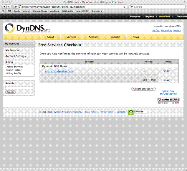
image005.jpg


6. Select the Activate Services button at the Free Services Checkout page.


7. You will then be brought to the Host Services page which will display the Hostname to WAN IP Address.

image006.jpg


Personal Router Configuration


8. Login to your personal router and go to the Dynamic DNS section.  I used a Netgear WNR3500 Gigabit Router ($99.99) athttp://www.newegg.com/Product/Product.aspx?Item=N82E16833122220).  The Dynamic DNS Service is the most reliable but you can also install the service/software at https://www.dyndns.com/support/clients/ on a host. The supported hosts are Windows, Max OS X, Linux and UNIX.  This service is very important since it periodically checks your network's WAN IP address; if it sees that your WAN IP address has changed, it sends (updates) the new IP address to your hostname in your DynDNS.com account.


While still in the Dynamic DNS window on your router..


-Check mark Use a Dynamic DNS Service to enable the Dynamic DNS feature on your router.

-Enter the hostname that you created on your DynDNS account from step 4.

-Enter the username and password for your DynDNS account from step 1.

-Select the Apply button.

image007.jpg


9. Go to the Port Forwarding / Port Triggering section on your router.  Create a Port Forwarding entry.  In this example, I have created a Service called Remote_Desktop, Start \ End Ports of 3389 for RDP and the Server IP Address of my Virtual Machine which could be your vCenter Server.


Note: I have only gone through the process to setup Remote Desktop but many other ports can be forwarded.  A full list of ports is available at http://www.portforward.com/cports.htm.


Virtual Machine Configuration


10. Go to a command line and ping your full domain name.  It should resolve back to your WAN IP Address.


Note: You will only get a reply while on your local network and not from outside of your local network.


C:\>ping vm-demo.dynalias.com


Pinging vm-demo.dynalias.com [76.92.201.8] with 32 bytes of data:


Reply from 76.92.201.8: bytes=32 time=5ms TTL=128

Reply from 76.92.201.8: bytes=32 time=5ms TTL=128

Reply from 76.92.201.8: bytes=32 time=7ms TTL=128

Reply from 76.92.201.8: bytes=32 time=8ms TTL=128


Ping statistics for 76.92.201.8:

    Packets: Sent = 4, Received = 4, Lost = 0 (0% loss),

Approximate round trip times in milli-seconds:

    Minimum = 5ms, Maximum = 8ms, Average = 6ms


11. Go into System within the Control Panel and enable Remote Desktop by selecting the Remote tab, check mark Allow Users to Connect Remotely to This Computer under Remote Desktop and then select Users to allow within the Select Remote Users button.  Once completed, select the OK button to apply.


Note: I occasionally turn off the Windows Firewall under Windows Firewall within the Control Panel to test network connectivity.  The ability to ping over the LAN is not available while the Windows Firewall is in use.  After completing your testing, re-enable the Firewall.  There was a Remote Desktop Exception created within the Windows Firewall when we enabled Remote Desktop.


Remote Connection


12. Disconnect from your direct connect or Wireless network and connect via a broadband card or via a network outside of your home.  I am using a Verizon WWAN card.


13. Via the Windows Remote Desktop Connection client, list the host and domain name that you created in step 4.  The host and domain name that you created in step 4 will resolve to your WAN IP Address and forward the Remote Connection onto Port 3389.


14. You are now connected to your Virtual Machine desktop.  This is just an XP Virtual Machine that I will use as a portal to launch the vCenter Client.  I have shown the example below of a single vSphere Node before I add it to vCenter along with the GUI of my Primary Celerra and VNX Simulator. 

Intel SS4200-E Performance Review (For Home VMware ESXi Lab)

Here is the performance testing that I ran on my Intel SS4200-E NAS Server running EMC Life Line for my Home VMware ESXi Lab. 


I used Iozone Filesystem Benchmark (http://www.iozone.org) for the performance testing below.  The command with option that I used for this test was “iozone -Rab cifs_test.xls -i 0 -i 1 -+u -f Y:\cifs_test -q 64k -n 32M -g 1G –z” as an example.


CIFS performance testing on my SS4200-E (4 - 1TB Drives in RAID-5) with 512 MB (Standard) Cache and with 1 GB (Upgraded) Cache.  I observed a max write speed of 90.06 MB/sec and a max read speed of 53.17 MB/sec.

Momentus XT Hybrid Laptop Drive (Kind of Like FAST Cache)

A while back, I performed some extensive hard drive testing on one of my MacBook Pro laptops and noticed that some performance issues with Virtual Machines are due to hard drive performance.  A few weeks ago, I found the 500 GB 7200 RPM Momentus XT Hybrid Laptop Drive that uses 4GB of SLC NAND Solid State Memory.  Seagate calls this technique "adaptive memory" and states that the controller decides which particularly frequently requested data should be stored in the quick-acting flash memory.


I ordered it off of Newegg for $119.99 with a coupon and free ground shipping. 


Conclusion: I have listed the 5400, 7200 and 7200 Hybrid overview data (From Testing A Few Weekends Ago) below along with detailed performance reports (PDFs Attached).  I performed this testing on a MacBook Pro with 4 Cores and 8 GB of RAM.  My testing found a dramatic performance gain in Sequential Reads with the 7200 Hybrid drives.

5400 RPM Drive Test Results - Select to View PDF

7200 RPM Drive Test Results - Select to View PDF

7200 RPM Hybrid Drive Test Results - Select to View PDF


Momentus XT Hybrid Laptop Drive Main Information - http://www.seagate.com/www/en-us/products/laptops/laptop-hdd/

Momentus XT Hybrid Laptop Drive Purchase Information - http://www.newegg.com/Product/Product.aspx?Item=N82E16822148591


Key Specifications

            •           500GB, 320GB and 250GB hard drive capacity options

            •           4GB SLC NAND solid state memory

            •           7200-RPM spindle speed

            •           32MB of drive-level cache

            •           SATA 3Gb/s with Native Command Queuing


         Solid state hybrid drive delivers SSD-like performance with hard drive capacity options.

         Adaptive Memory technology customizes performance by aligning to user needs for overall improved system response.

         80 percent faster performance than traditional 7200-RPM drives in PCMark Vantage benchmark scores